Getting started
Hardware setup
To use Copilot, you need:
A Copilot
1 USB-C cable for control (only USB2 wiring needed)
Optionally, depending on your needs:
2 USB-C cables for power (power supply ↔ Copilot ↔ DUT)
2 Barrel jack cables for additional power supply
3+ wires for FTDI (debug UART)
Wires for additional GPIOs
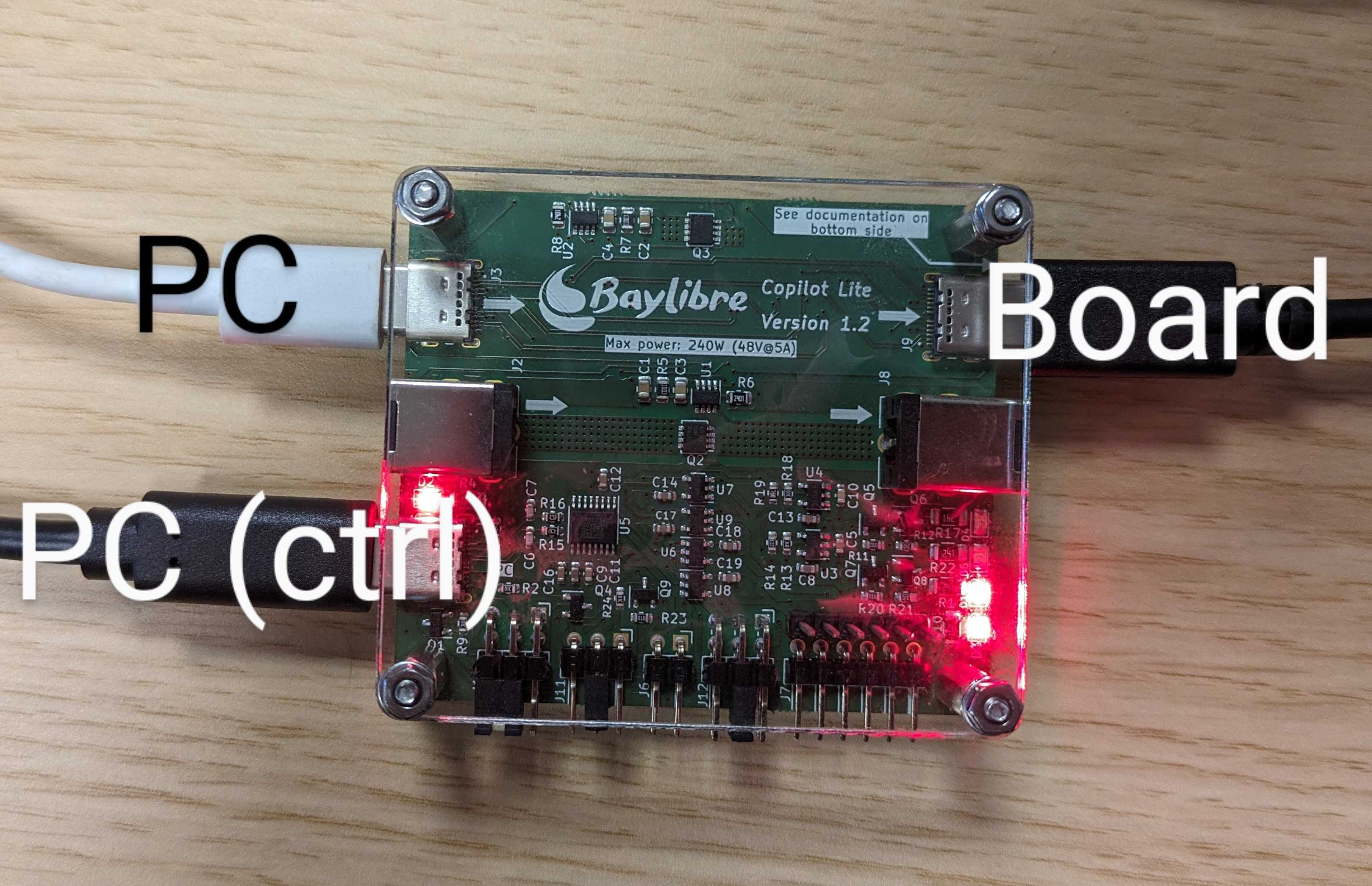
Plug it in as following:
Note
By default, the USB and barrel jack power passthroughs are controlled by a single GPIO. To enable the USB and barrel jack power passthroughs follow the steps in Switch power.
Warning
Even if USB-C is a reversible connector, the USB-C cables can only work
in one direction. If USB power supply seems not working after enabling.
Try flipping one USB-C cable on either J9 or J3.
Warning
Copilot is not designed to support power passthrough through the USB and barrel jack connectors at the same time. It is therefore good practice to only jump a single pair of pins at a time
Basic documentation has been silk screened onto both sides of the board.
Design files, along with the latest schematics and the interactive BOM, are manually generated for each release and available on the releases page. The interactive BOM features an annotated diagram of the board including the silk screen, both sides of the board and searchable references.
Udev rules
Generally, a PC running Linux has multiple GPIOs in the system. To easily identify Copilot, create some user-friendly symlinks with udev as follows.
Add the
/etc/udev/rules.d/70-copilot.rulesudev rules to your system:ACTION=="remove", GOTO="copilot_end" # Match Copilot USB devices SUBSYSTEMS=="usb", ATTRS{manufacturer}=="Bay[lL]ibre", ATTRS{product}=="Bay[lL]ibre Copilot*", ENV{IS_COPILOT}="1", ENV{ID_USB_SERIAL_SHORT}="$attr{serial}" # Enable Copilot gpio access via uaccess and copilot symlink ENV{IS_COPILOT}=="1", SUBSYSTEMS=="gpio", MODE="0660", SYMLINK+="copilot/by-id/$env{ID_USB_SERIAL_SHORT}/gpiochip", TAG+="uaccess" # Create Copilot tty symlink ENV{IS_COPILOT}=="1", SUBSYSTEMS=="tty", SYMLINK+="copilot/by-id/$env{ID_USB_SERIAL_SHORT}/tty" LABEL="copilot_end"
Note
For users who rely on the
plugdevgroup, use the following rules instead:# Match Copilot USB devices SUBSYSTEMS=="usb", ATTRS{manufacturer}=="Bay[lL]ibre", ATTRS{product}=="Bay[lL]ibre Copilot*", ENV{IS_COPILOT}="1", ENV{ID_USB_SERIAL_SHORT}="$attr{serial}" # Enable Copilot gpio access for the plugdev group and copilot symlink ENV{IS_COPILOT}=="1", SUBSYSTEMS=="gpio", MODE="0660", GROUP="plugdev", SYMLINK+="copilot/by-id/$env{ID_USB_SERIAL_SHORT}/gpiochip" # Create Copilot tty symlink ENV{IS_COPILOT}=="1", SUBSYSTEMS=="tty", SYMLINK+="copilot/by-id/$env{ID_USB_SERIAL_SHORT}/tty"
uaccessshould be used instead ofplugdev. For more information, see: https://github.com/systemd/systemd/issues/4288Reload the udev rules with:
sudo udevadm control --reload sudo udevadm trigger
This creates an entry in /dev/copilot/by-id/<copilot_id> where
<copilot_id> is an unique serial number.
Switch power
Now that the udev rules have been installed, we can interact with Copilot using the
standard libgpiod-utils, such as gpioset.
Start by finding the serial number for your Copilot (e.g. D30HF04Y) and
export it as an environment variable:
tree /dev/copilot/
/dev/copilot/
└── by-id
    └── D30HF04Y
        ├── gpiochip -> ../../../gpiochip0
        └── tty -> ../../../ttyUSB1
export ID_USB_SERIAL_SHORT="D30HF04Y"
Power over the USB and barrel jack connectors may be independently configured using the J1 header to be either controlled by a single shared GPIO or always passthrough power. See the silk screen at the top of the rear side of the board.
By default, the USB and barrel jack power passthroughs are controlled by your PC using a single GPIO that is disabled after power cycling Copilot. The passthroughs can be powered by enabling the GPIO as follows:
gpioset --hold-period=20ms -t0 --chip /dev/copilot/by-id/${ID_USB_SERIAL_SHORT}/gpiochip 0=1
Note
For older versions of libgpiod-utils, (before v2.0), use the following
instead:
gpioset /dev/copilot/by-id/${ID_USB_SERIAL_SHORT}/gpiochip 0=1
To disable the barrel jack power passthrough, use 0=0 instead:
gpioset --hold-period=20ms -t0 --chip /dev/copilot/by-id/${ID_USB_SERIAL_SHORT}/gpiochip 0=0
Helper script
copilot.sh is an example helper script which can either reboot or power off
a board connected to Copilot.
It can be used with:
# to reboot
copilot.sh reboot
# to poweroff
copilot.sh poweroff
The contents of copilot.sh could be as following:
#!/bin/bash

# Set a default value, but don't overwrite ID_USB_SERIAL_SHORT
# if it's already set
: ${ID_USB_SERIAL_SHORT:="D30HF04Y"}

usage()
{
    echo "Usage: ${0##*/} reboot|poweroff"
}

if [[ $# -ne 1 ]]; then
    usage
    exit 1
fi

do_poweroff()
{
    gpioset --hold-period=20ms -t0 --chip /dev/copilot/by-id/${ID_USB_SERIAL_SHORT}/gpiochip 0=0
    # or for libgpiod v < 2.0
    #gpioset /dev/copilot/by-id/${ID_USB_SERIAL_SHORT}/gpiochip 0=0
}

do_poweron()
{
    gpioset --hold-period=20ms -t0 --chip /dev/copilot/by-id/${ID_USB_SERIAL_SHORT}/gpiochip 0=1
    # or for libgpiod v < 2.0
    #gpioset /dev/copilot/by-id/${ID_USB_SERIAL_SHORT}/gpiochip 0=1
}

do_reboot()
{
    do_poweroff
    # maybe wait until all power drained from the board
    #sleep 5
    do_poweron
}

case "$1" in
    "reboot") do_reboot;;
    "poweroff") do_poweroff;;
    *) usage; exit 1;;

esac
Connect to a UART
Connect to the Copilot UART using the left-most header at the bottom of the PCB (J4). The pins are documented on the bottom of the PCB. The voltage can be selected on the next header.
To use the connected UART in Linux you can use your favorite terminal program
with the device /dev/copilot/by-id/${ID_USB_SERIAL_SHORT}/tty, in this
example we are using tio:
tio /dev/copilot/by-id/${ID_USB_SERIAL_SHORT}/tty